
MTP DIY Digital Cluster Full Install and Setup Tutorial for GM 99-06 Trucks
Keep in mind this post is very much a “work in progress”, better and clearer instructions will be provided with time, however on a short notice this is what I could put together based on my build and work in progress software.
BEFORE YOU DECIDE TO BUY OR INSTALL ANY OF THE COMPONENTS
READ VERY CAREFULLY:
____________________________________
as of 22/10/2020 The MTP Cluster Software is not released yet and is still being developed!
Continue at your own discretion.
DISCLAIMER
By reading this you(the reader / customer) agree and understand that this product is not a finished product, you may experience: software bugs, hardware and software issues, issues in general and difficulties while installing, you agree to read through the common issues below before you buy or install anything.
You (the reader / customer) takes full responsibility for the parts you are installing and agree that MaxTunePerformance or maxtuneperformance.com or its owner(Tony Enns) holds no responsibility for consequences, legal, or other, of such use and/or misuse.
MTP products and software are sold for off-road use only.
Items sold for off-road use only are illegal in multiple states and provinces and are only intended for racing vehicles which may never be used on a public road.
By purchasing any MTP aftermarket product, you (the reader / customer) takes full responsibility for any use, and/or misuse of the product and agrees that MaxTunePerformance or maxtuneperformance.com holds no responsibility for any consequences, legal, or other, of such use and/or misuse.
____________________________________
End of Disclaimer.
Now that we got that out of the way! On this page you should find just about everything to install the DIY cluster, keep in mind this is the first iteration of the hardware we chose and the earliest version of our MTP Cluster software we are using. Later iterations will be cleaner, better and easier to use.
Here I will provide a list of current issues and bugs that you will or may experience with the hardware and current software version (v0.1 – 15/10/2020)
List of current issues and things to keep in mind:
with the current software (v0.1 – 15/10/2020) and default operating system, load time / boot up time takes long (30-40+ seconds) or longer, we will do our best to improve this with future software and hardware updates but until then be ready to wait a little while for it to turn on, just like restarting / turning on your phone can take a while.
most 1999-2002 models will not display oil pressure without some additional modifications (which will be explained below)
The current software is still missing lots of features that will be present in newer versions.
Some inputs and parameters like turn signals, odometer, light switch dimming are not integrated into v0.1 of the software, future software versions will have them integrated or will have a separate hardware to fix this.
v0.1 of the software does not officially support 2003-2006 year models yet, the software should work, but currently(at the time of writing) it only has 1999-2002 cluster designs integrated, you will have to switch to an 1999-2002 cluster bezel to complete the look while we update the software sometime soon in the future, this is probably already fixed in v0.2.
Installation of the screen / components requires permanent dashboard modification (the dash modifications are not visible if you decide to go back to an OEM cluster at any time) electrical connections stay 100% OEM with the current v0.1 version of hardware and software.
____________________________________
Additional Info:
The MTP Cluster Software license is bound to your vehicle’s vin number, this is a safety measure to prevent anyone from “cloning” and pirating our software, keep in mind this is a permanent license, if you decide to sell your cluster to a different individual later, this new owner will have to buy a “vin-license-activation” to activate the cluster for their vehicle. (but it will be cheaper than buying a new license)
Changing/Replacing your vehicles PCM to any different vin number may cause the MTP Cluster Software to become de-activated until the vin numbers match again with the software, you can however not activate 2 clusters using the same license and same vin, the license is a one time use
Incase of the SD / Hardware Failure, after replacing bad hardware you will most likely be required to buy the “vin-license-activation” to re-active your same vin number.
To install the software to the “raspberry pi” you will require a computer / laptop, internet connection, a spare keyboard and mouse.
Updates will require a computer / laptop, internet connection, a keyboard and mouse, updates will also revalidate your vin number.
____________________________________
The Install
Now that we got the important but somewhat boring information out of the way, here comes a somewhat detailed full install tutorial, it will be in 2 parts.
Buy the hardware and software:
We will assume you bought the same hardware as we link to in our shop, here’s a link to the required hardware and software: (They redirect to amazon where you can buy them)
Use coupon MTP15OFF for 15% off your MTP Cluster Software Pre-Order
https://maxtuneperformance.com/index.php/product-category/digital-clusters/diy-cluster-parts/diy-clusterkit-9906/
Part 1:
Downloading, Installing and setting up the software
Part 2:
Installing the hardware / cluster componenets, screen, raspberry pi, inverter, wiring..etc
Another note: There is no “official way” of installing the DIY MTP Cluster, all the pictures, details and text displayed here are just for reference, my install was very “thrown together” due to multiple months of prototyping.
So take that as an opportunity to do a cleaner and better install than I did.
(For part 2) Before doing any wiring and connecting, please disconnect the battery or – negative battery terminal off your vehicle.
Part 1 (Downloading, Installing and setting up the software):
PART 1 IS A WORK IN PROGRESS DUE TO SOFTWARE NOT BEING RELEASED YET, PLEASE CHECK BACK LATER FOR UPDATED DETAILS.
To setup the raspberry pi you will need a TV or monitor / screen that has an HDMI connection, if you don’t have one, we can use the screen from the MTP Cluster Kit, please look at “Part 2” which shows you the “pre-setup” for the electronics, including the screen, you will simply be plugging in the HDMI to the raspberry pi and the power supply to a normal wall outlet, powering it will turn it on automatically, so power it after you’re ready to setup the raspberry pi.
The method above is also recommended to test the screen, raspberry pi, components and software before installing it into your vehicle.
Before we do any MTP installation work, assemble and setup your raspberry pi with the included case, instead of setting up the original Rasbian Operating System, skip that step, and read below how to setup our modified operating system with our included software. Here’s a tutorial for the main setup for CanaKit Raspberry Pi 4:
https://www.youtube.com/watch?v=Wb1YForDARU
In my build I used the Vilros Kit, any kit should work since there’s not too many differences between the brands, but do your research for the specific kit you bought to avoid any problems.
After you download our premade OS .img file that includes the MTP Software, you should be able to Flash it.
To flash it you will need to download Etcher for your computer or laptop, Etcher is used to flash the OS .img file onto the mini SD card (the raspberry pi kit usually includes an USB sd card reader).
Select flash from file, browse to the MTP_OS_SoftwareV01.img file you downloaded in the previous step and select it. (might be named slightly different for later versions)


After its finished, safely eject, remove and then insert the mini SD card into the raspberry pi and power it ON by plugging in a powered USB-C cable (power with PC or through included adapter)
Connect your usb keyboard and mouse to the raspberry pi if you havent already.
You will need an internet connection, you can setup wireless on the raspberry pi’s desktop, click on the wireless icon on the top right and pick your wifi, currently I can’t provide screenshots for this but its pretty straight forward. Alternative option is to connect an ethernet cable directly from your raspberry pi to your router.

After internet connection is setup, you will need to restart the pi.
After the boot (40 seconds or so in v0.1) it should automatically start the MTP Cluster Software, it will prompt you to enter your license key.
(After purchasing the software you will receive a license key, if you pre-ordered the software you will be sent a license key upon software release)

You may setup the raspberry pi temporarily inside your vehicle for this next step.
Upon entering the license key the MTP software will confirm the key in our database, however the license won’t be used until you plug it into a vehicle where it will be bound to the vehicles vin. To bind the license with the vin you will also require internet during this step.
NOTE: Only plug it into the vehicle you want the license to be permanently bound too! If you plug it into another vehicle you will waste your license, in such cases we can offer support online.
Part 2 (Cluster Installation)
Pre-hardware setup
Setting up the LCD Screen and LCD Controller Board
This just shows you how the connection goes, you will need to disconnect them and connect them inside the vehicle again later in the install after the LCD controller board is secured to your dash
Screen backside side:
Connector slides in easily, be careful with the thin wires to not accidentally rip them out, avoid pulling on them if removing connector.

and for the other end of the cable, the LCD Board Connector:

Now you know how to connect the LCD screen and the LCD controller, later you will have to plug in an HDMI to mini-HDMI (included in the raspberry pi kit) and your 12v 5a power supply into the LCD controller as well, there’s a “button board” included with the LCD screen used to change settings like a normal monitor, I used it once to bench test my cluster to make sure the input was set to HDMI, however you will probably not be needing it for a normal install. But don’t throw it away incase you need it to troubleshoot the screen.
Vehicle Dash Preparation & Cluster Installation
Start by taking apart your truck / vehicles dash:
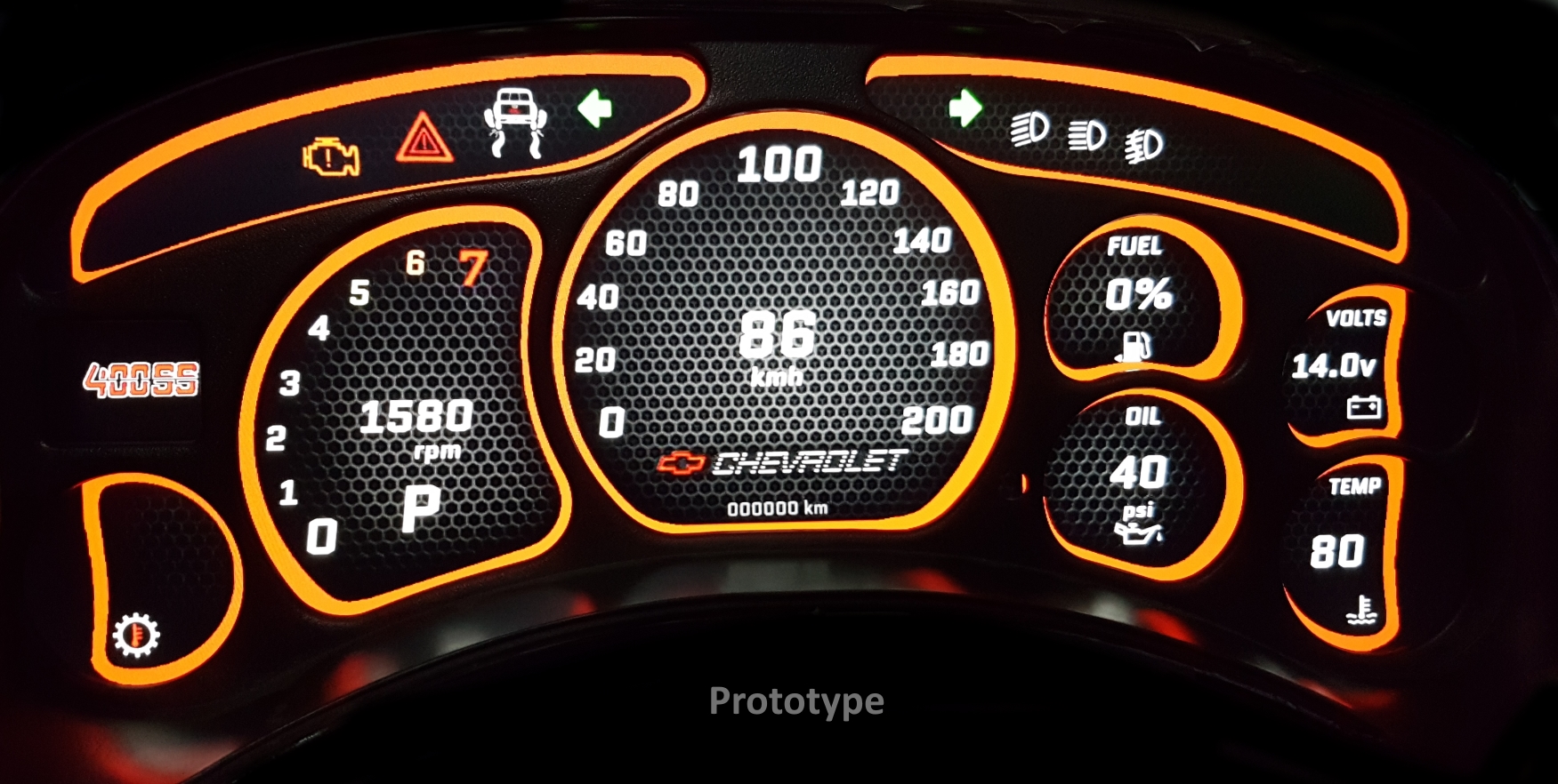
Clearly mine already has the digital cluster however ignore the nice beautiful digital cluster for now and continue, the process is the same with your OEM cluster / dash.


So far so good!
I did state we need to do some modifications to the dash.. So..
Before we can install anything we need to make room for the big screen, we do this by cutting away the top bracket / metal bridge piece of the dash that’s above the cluster, here’s images showing where to cut.
You will also new a couple “L” brackets, in my case I had something laying around. I never claimed it would look pretty behind the cluster!
Feel free to modify the brackets and cuts to your liking, this is just how I did my prototype personally, there is a lot of room for improvement.
We will provide more cleaner and detailed install instructions in the future, this will have to do for now tho.
For this step you will need some cutting tool(s), I used a combination of a dremel and sheet metal cutting scissors, I would recommend you take off the entire top skin of your dashboard before proceeding.
To take off the top dashboard layer of your truck, here’s a tutorial:
https://sparkys-answers.com/2011/03/2004-chevrolet-silverado-dash-cover.html
or a youtube video:
https://www.youtube.com/watch?v=CwaQSJZymFU
In this photos I show my dashboard with the top layer still on, but I can assure you I took it off during the dremel cutting part.


Now in my prototype you can see I already attached the LCD Controller Board, however as stated its a prototype, I would suggest you get get some plastic brackets to properly secure it and to make sure it doesn’t short on anything metal. Our future DIY kits will come with 3D printed mounting cases for all the electronics to avoid any difficulties while installing. This step is something for you to figure out, a trip to the hardware store should give you enough ideas, just keep in mind the LCD controller board must be mounted close to the screen / rear screen connector.
After you finish with the modification and your screen fits in between the slits and sits ontop of your steering column, you can put the top layer on temporarily to test fit the screen for the next step
Lets continue to the next step..
I have 3 words, Rubber. Foam. Tape.

The rubber foam tape helps with making any contact points soft, and more importantly will make sure we don’t get vibration noises.
I used a lot of it and so should you.
Next step will be to lower the steering column, yup even after removing the top metal bridge our screen will still not clear 100%, so my fix was to lower the steering column, this can be done by unbolting the 2 nuts in the front and loosening the couple bolts near the end of the steering column, we just need to push the steering column far enough down to slip a couple washers onto the threads between the column bracket and the dash bracket.

After you struggle with that, (I know I did), put the nuts back on the thread and tighten everything back up, at this point you can check the clearance with the screen ontop of the column and in between the slits, the slits give you enough room to slide it a bit left or right to adjust it later.
Later you should add 2 short L brackets or something to either side of the screen to hold it from sliding left or right, I didn’t do this since it felt like my bezel held my screen tight enough. Once again this is an afterthought for me, since there is lot of room for improvement.
Next step is to find a place to wire in your Inverter which will be used to power the screen and the raspberry pi.
The location of the inverter is up to you, I saw there is a bracket behind the cluster that the inverter could probably fit into, however for my case I put it in my center console, since I have a 03′ style console in my 00′ sierra, I saw there was more than enough room under it for some electronics.


The inverter had a cigarette lighter connector which I snipped off and was left with a red 12v wire and a black ground wire, I didn’t want the screen to be on 24/7 obviously so I ran a wire from the fuse box (ignition switched wire) to a relay, a 12v constant 40a fused wire from the battery. (in my case I have a separate fuse box to prototype my electronics).
Here’s a simple diagram, left side shows the only wiring you need to do for the basic cluster setup, additional wiring may be needed for turn signals to show on the cluster as well as for oil pressure to work on some 99-02 models.

Run your 12v5a power supply cable to the screen LCD controller board as well as the mini-HDMI to HDMI to your LCD controller board
Run an USB-C cable from your inverter to the raspberry pi
and Run the OBDLink SX Cable from the raspberry pi to your vehicles OBDII connector or if you bought the Y Splitter to retain the OEM OBD port, install that first, this lets you keep the OBD port open if you wanna hook up scanners, however using other OBD devices like scanners or HPTuners may interfere with the cluster or vice versa, keep that in mind.
Plug in your screen and position it against the L brackets you installed earlier, before you tidy everything up its a good idea to put your Battery Cable back on and test it first.

Go through the MTP Cluster VIN Setup if you haven’t already and now your ready to align your oem cluster bezel ontop of the screen. Before you do that, here’s instructions to prepare the bezel so it can sit flush against the screen:


You can also see the clips I cut in the image below:

The bezel will be pushing against the screen with medium pressure, use rubber foam tape to soften the pressure and this will help hold the screen in place later when you bolt the cluster on, if you made the L brackets too deep you will need to add extra material to hold it in place better, however the thick rubber foam tape lets you have some error and should push against it even if placed somewhat deep, however the tighter the fit the better and more flush the bezel will look against the screen.
I would also recommend to put foam tape along the whole bottom edge of the screen as well as the top edge, since it may rub both against the top of the dash as well as the 3 points it sits on the bottom.

Sadly the screen does not cover 100% of the cluster, you can hide the edges using glossy black tape on the screen edge to make it less obvious, for now we could not find any screens that would fit the slim measurements required for the 99-06 models. This could change in the future if we get special hardware made but for now this is what we’re stuck with.
Turn everything on, test the cluster and align the screen by sliding it either left or right and rotating it as needed before the bolt the bezel lens to hold it in place.
For now the basic cluster is complete..
..however Part 3 will cover how to hook up external inputs like Air/Fuel Gauge as well as non-OBD inputs like turn signals and some seperate stuff like screen dimming and of course Oil Pressure for the 99-02 platform.


and done!
We might have skipped some details here and there, we will be updating this post over the next few weeks to improve the installation instructions with more details and pictures as well as post Part 3.
Part 3 – Connecting external inputs (Coming soon)